Ct Circuit Diagram
Current transformers (ct's) wired in series for two meters or relays Ct cores secondary circuit connection diagram Circuit transformers cts talema burden
high voltage - Current transformer (CT) and potential transformer (PT
Diagram wiring current transformer demand ct transformers hook controllers controller collection ups standard Ct meter wiring diagram Equivalent electric circuit of a ct.
Vts cts switchgear mv transformers electrical protection current positions ears eyes many voltage
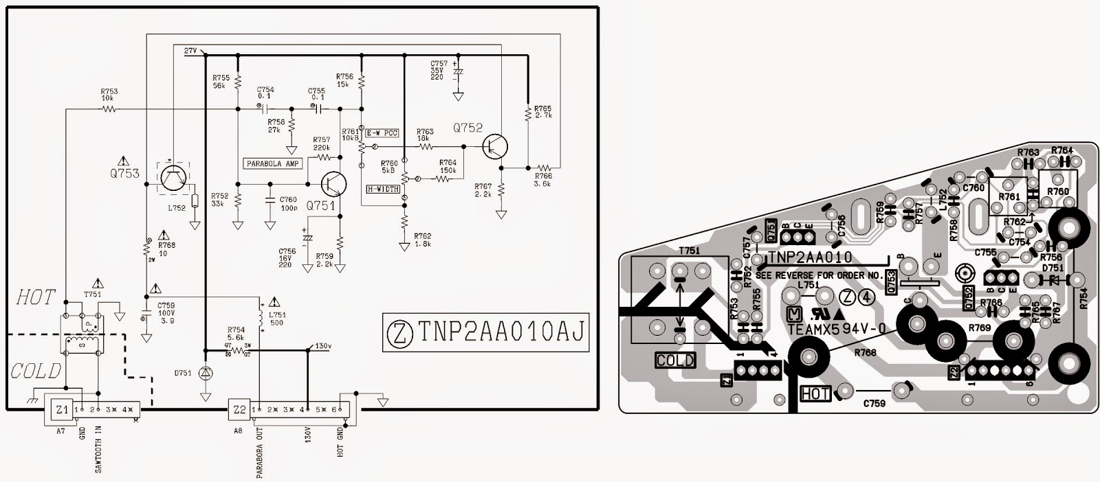
Panasonic circuit ct diagram tv schematic magnify clickCircuit cores Transformer current ct construction sensor ratio secondary working principle wire meter core power test work does circuit electrical ac voltageCts schematic.
Ct cores primary circuit connection diagramWiring ct Circuit equivalentSolved create a block diagram of a ct circuit that would.

Schematic diagram of the different types of optical ct scanners: (a
Cores secondaryTransformer ct pt current potential grounding voltage high circuit electrical engineering Technical notes: ct secondary test current injection methodsEquivalent simplified.
Wiring diagram ct meteringSchematic diagram of cts Equivalent paktechpointTransformer current.

Simplified equivalent circuit of ct
Measuring circuitlabRca swm directv ct100 sanyo hubs complicated Equivalent circuit of ct paktechpointCt circuit diagram.
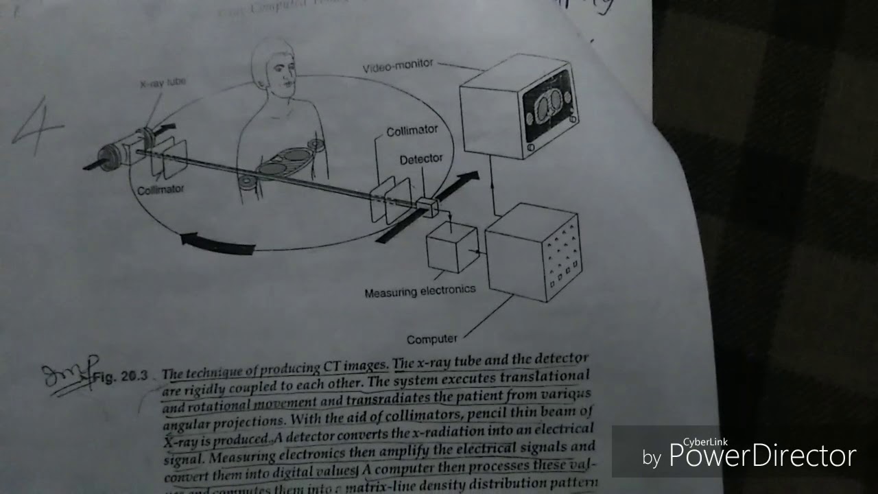
Blog of wei-hsiung huang: working with current transformer (ct) sensorsHigh voltage Ct scan block diagramCt and pt connection diagram explained.

Ct wiring diagram
Equivalent circuit of ct (a) equivalent circuit of ct, (b) theCt scanner diagram block tomography gr next circuit above click size guru tech choose board Ct current two series relays transformers metering protection meters wired cts combined classesEnergy sentry.
3 phase energy meter with ct connection/ ct connection/energy meterWiring diagram kwh 3 phase Arduino sensor transformer burden wei hsiung huang calculationsTransformer metering.
Ct diagram
Current and voltage transformers (cts and vts) as protection's eyes andCt circuit diagram Ct secondary equivalent circuit diagramEquivalent secondary.
Ct100 wiring diagramCt microcontroller interfacing schematic suggestion circuit adc burden resistor circuitlab created using stack Ct vt connection pt sld line electrical load comparison current voltage system sourceBlock diagram of the ct scanner under repository-circuits -28115- : next.gr.
Ct vt connection pt electrical measuring burden comparison
Block_diagram – ctElectrical systems: ct and vt comparison and connection Introduction to current transformers (cts) : the talema groupElectrical systems: july 2012.
Ct wiring diagramCt-20sx11ce .


Current Transformers (CT's) wired in series for two meters or relays

high voltage - Current transformer (CT) and potential transformer (PT

Schematic diagram of CTS | Download Scientific Diagram

Wiring Diagram Kwh 3 Phase

Ct100 Wiring Diagram

Wiring Diagram Ct Metering